|
Custom Motor Mounts - Mount any Motor/Tranny in any Frame-This is Wyatt's article on making custom motor mounts. This will also work on tranny mounts, suspension links, really any kind of mount... This is really important tech! -Trent- by Wyatt Pemberton aka InDaShop I’m sure there are 1000 ways to skin this cat, but here is my cheap, straightforward way on making custom motor mounts. This is my pretty dang easy way to simplify putting that Hemi in that “A”, or that SBC in a Ford. For this example I put a Caddy 500 in a ’49 Chevy Pickup. The only limit is your imagination. Materials: 3”x 3/8” mild steel strap 1 ¾” DOM tubing that is 1/8” wall (.125). Energy Suspension Bushing # 3.2124G (This is a 1973-1987 Chevy pickup rear leaf spring eye bushing, appox. $3.50 for a set of two) 3 ½”s of Closet/Clothes hanging dowel Tools: Ability to cut and grind metal “Chopsaw” Ability to stick one piece of metal to another “Welder” Drill Tape measure
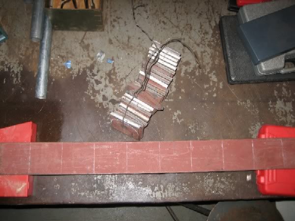
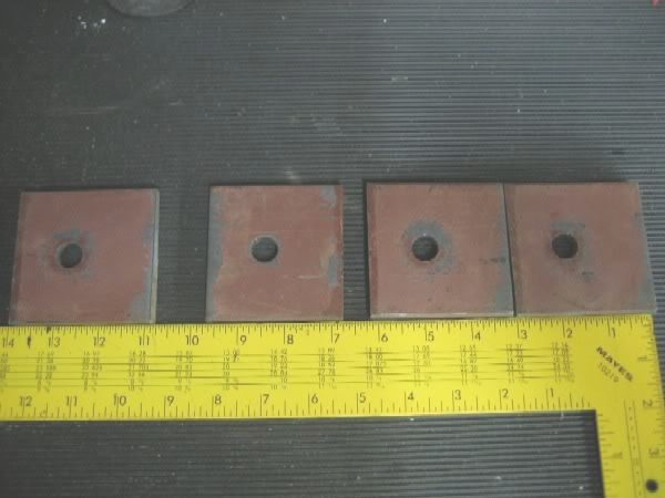
I start out by getting a piece of 3”x 3/8” piece of mild steel strap and mark it to cut every 3 inches. These will be the mounting ears on the frame that the motor mount or transmission cross-member will bolt to. I prefer to make a pile of these when I do it. They come in handy for everything from motor and tranny mounts, to a way to mount a roll cage to your frame. I have access to an iron worker to shear these, but a torch/sawzall/grinder/plasma would all work the same. At this point in time I also drill them all.
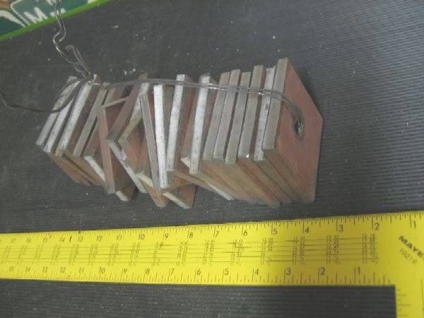
For storage and organization I run a piece of bailing wire through the drilled holes and hang the whole shebang on a nail by my work bench.
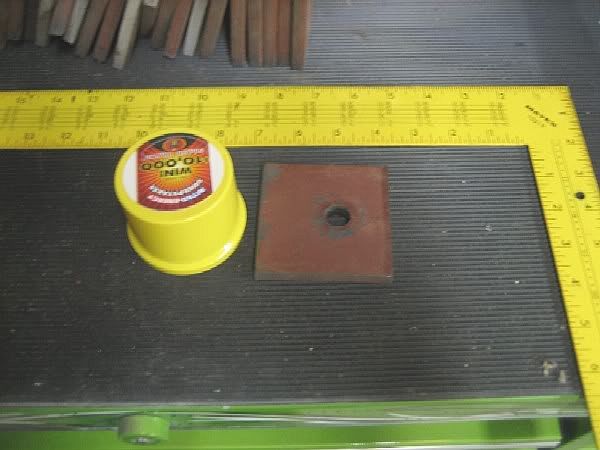
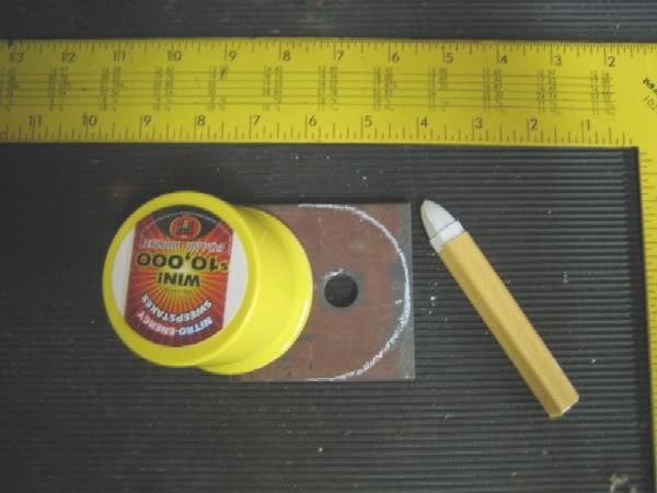
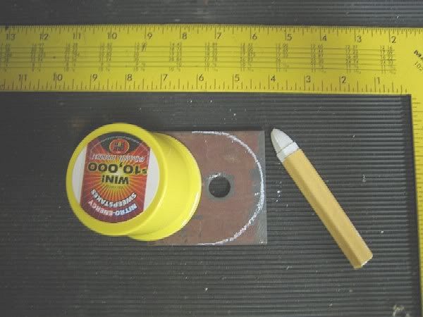
Now you can make them pretty for use on your frame. I use a spray can lid to draw a half circle of what needs to be cut off. Torch and grinder, and you’re looking pretty.
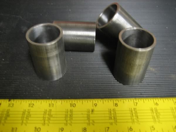
Now the mounting ears are taken care of. Lets look at the bushings, and sleeves to isolate the motor and tranny vibrations from the frame and you. I use 1 ¾” DOM (Drawn Over Mandrel) tubing which is seamless, and an Energy Suspension poly bushing to accomplish this. Now I know of guys using 1 ¾” HREW (Hot Rolled Electric Welded) tubing or stuff with seams, because they claim the welded seam doesn’t allow the bushing to spin after they hammer it in. I prefer DOM because it will never split and why worry about the bushing spinning, it won’t effect anything. I take my length of DOM and mark it every 3”s and chop it with my chop saw. Then emery cloth the edges and inside a bit.
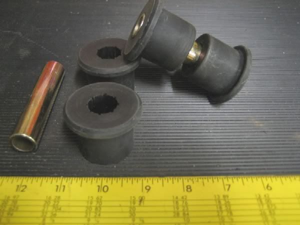
For my bushing I use Energy Suspension bushing # 3.2124G, which is a 1 ½” poly bushing for Chevy Truck rear leaf springs. I buy in bulk but they are like $3.50 for a pair. And it takes two pair for this set up. So be ready to mortgage the house for $7. EDIT I just found out ES stopped selling direct to the public, you have to go through a distributor, sorry, but the part number is still the same you just get dinged a bit more for them.
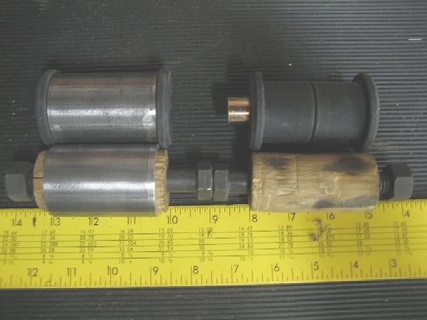
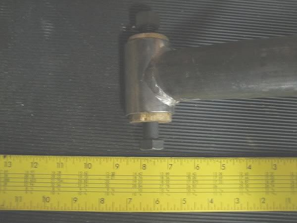
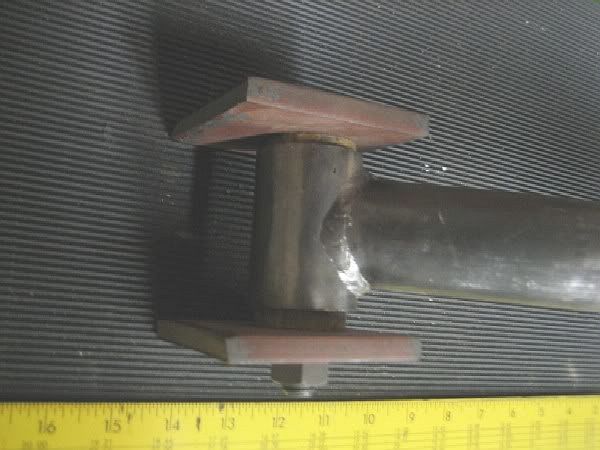
Now lastly I cut some clothes/closet dowel to help me weld with. I make the dowel the width of what my bushings will be in the DOM. So they are proud each end by about ¼”. I do this so I can bolt the mounting tabs to the DOM to weld to the frame without worry of ruining my bushings. Here is a pic of Clockwise from top: DOM with Bushing installed, Bushing unistalled, Dowel drilled for bolt, Dowel installed in DOM ready for welding.
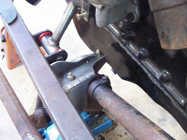
Here I have fabricated a tranny crossmember and for the sake of demonstration I am showing how I bolt the ears on just prior to welding to the frame.
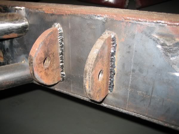
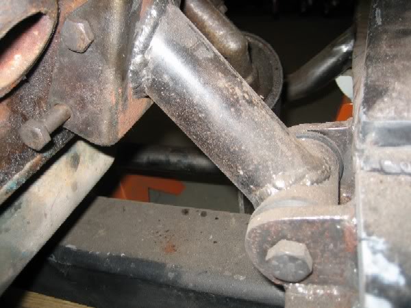
Here is a pic of the mounting tabs welded to the frame after I have removed the tranny crossmember and dowel setup.
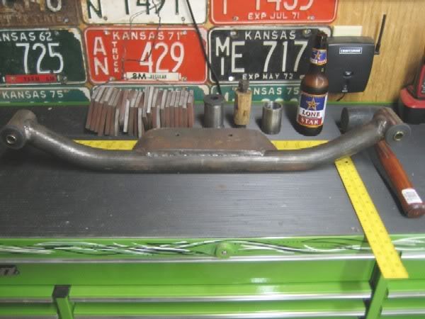
For my tranny crossmembers I use the DOM and measure from side to side in the frame and cut to fit. I then weld a piece of the flat 3”x3/8” strap to this tube with mounting holes to support the transmission. Here is the basic mess of pieces I use to make this happen.
For the engine I take whatever motor mount the engine uses stock. In my example I used the old trashed ones that came with a 500 Caddy I came across. I cut the rubber isolator off and got it to where all I had left of the stock mount was the steel that bolts to the engine block. I positioned the engine where it was, where I wanted it, left/right/up/down/front/back. Took measurements and used my chop saw to cut the pieces of 1 ¾ DOM that went from the Bushing/mounting ears assembly up to what was left of the stock motor mount.
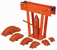
When messing with tubing you don’t need a holesaw jig or even a bad ass bender to make it work. I do have these tools, but this tranny crossmember I made with the 12 ton HF bender which I got for around $50. For lots of use I recommend welding a thicker plate in the bottom, as the stock one will bend pretty easy.
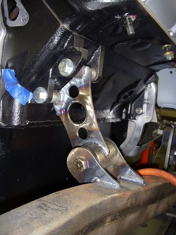
And for coping the ends of the pipe I use the chopsaw method. I’ve attached below what I saved from another website years ago, and have printed and laying around various places in my shop for easy access. Chopsaw method: The chop saw method, if understood, is a science. With known tube size and joint angle, tube can be notched with great accuracy. The notch is achieved by cutting two opposing angles on one end of a piece of tube, to form a point. The cross-section of this cut will be an elliptical cut due to the shape of the tube. Changes in both of the two angled cuts must be made for the intersection angle and the size of the two tubes being joined. The only real limitation is the max angle of the chop saw. You start with what I call the base angle. This is the angle of both cuts if the joint was 90*. For an example, I am fitting Two tubes together that are both 1.75", at an 90* joint. The base angle, or the angle of both cuts is 28*. These two cuts must meet at a point, and the point must also be centered on the tube. Remember your base angle will change with the tube being cut and the tube that you are fitting to. Here are a few examples of base angles... 2.0" to 2.0" tube, base angle of 30* 1.75" to 1.75" tube, base angle of 28* 1.5" to 1.5" tube, base angle of 26* 1.25" to 1.25" tube, base angle of 22.5* 1" to 1" tube, Base angle of 20* Now to fit different size tubes together 1.75" to 2" tube, base angle of 25* 1.75" to 1.25" tube, base angle of 45* 1.25" to 1.75 tube, base angle of 20* 1" to 2" tube, base angle of 12* What if instead of a "T" joint, I want the notched tube at a 15* angle with my first 1.75" tube???? You must start with your base angle, which was 28* for 1.75"(remember above), and subtract 15* from one cut, and add 15* to the other cut to form a perfect notch. So now I must make a 13* cut and an 43* cut with the point centered on the tube. Perfect coped joint, with no grinding. By the way... I saw Ray "HotRodChassis" over at Hot Rod Chassis & Cycle Is using this type of mount on a new car they are building. Much prettier execution than mine.
And another from Brian "Kustm52"
Oh yeah you can do innumerable things with this tech. Energy Suspension carries a huge amount of bushings. You can use smaller or larger tubing to make even more versatile setups. I like what I use the 1 3/4 DOM with 1/8 wall and the 1 1/2 bushings but the fact is Energy Suspension makes tons an tons on various sizes of bushing that are cheap that you can make work for everything you can dream up. In this instance I made motor mounts and tranny mounts, but nothing says you can't make suspension links or isolate you cab, or roll bar or gas tank from vibration with this same idea. Link mounts? Everyone is wanting to fab link mounts this is exactly how they are done. Same DOM, same Bushing and locate your rear axle with them. Tons of uses. I got asked a couple questons and wanted to address them, as I glossed over these details. How did you locate where you center punched and drilled the mount tabs? I initially took my bushing and positioned it where the radius of the rounded tab and the bushing "Looked" best. It came out to be about an 1 1/4" for the front edge, or 1 3/4" from the back edge. The beauty of this is you can position the hole whereever you need it and make your brackets look however you want. Shoot, maltese crosses and skulls with the bolt going through the eye socket if you are real hardcore. What size drill bit was used & through bolt? The bushing I listed is for a 9/16" bolt. I used the iron worker to punch the holes, but you could just as easy drill them with a 9/16" drill bit. For the bolts I use standard garden variety Grade 8's. I get most of my stuff from either Fastenal, Ace Hardware, or if I have a big enough order this local place here in Houston. I haven't got to the level of trust with fasteners from Lowes or HD. As 57JoeFoMoPar pointed out you are putting these bolts in shear. I actually think its double shear, but the technical terms still stump me sometimes. I'd think you'd be blown away if you had a motor that would torque hard enough, enough times to snap a bolt 9/16" Grade 8. Also as the bushings wear and get old and say, they do fail. The drivetrain is still "Captured" and won't flail around on you. Just go get another CHEAP bushing and you're back in business. If this help one guy, its a success. As for me just trying to spread the gospel. TIP Ok, so a little trick I started using recently for making my tabs with a nice radius. Here is a pic of what I used to do, and then used a torch to follow the line.
If you are cutting your circle with a plasma, use a socket (1" smaller than the circle needed, assuming your plasma cuts 1/2" off in the tip like mine) rather than the paint top. Use a clamp to clamp the socket to the plate. Drag the plasma around the socket. Clear as mud? You can also do the same trick with your Gas Ax but you'll need a socket that is like 1/4" smaller than the radius you are cutting. I owe this tip to my buddy John G. Also Thought these additional part numbers may helps some folks who want to use smaller tubing for this. Bushings for 1 1/2" I.D. tubing with a steel sleeve for 9/16 bolt. Energy Suspension Part# 3.2106G Bushings for 1 1/4" I.D. tubing with a steel sleeve for 9/16 bolt. Energy Suspension Part# 4.2129G Return from Custom Motor Mounts to Hot Rod Engines
|
